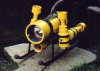
my mockup ROV

What are you working on .... Show off your Rov's Projects here.
User avatar
one mere mortal
Posts: 8
Joined: Sep 16th, 2011, 3:22 pm
Location: Connecticut

my mockup ROV

Post by one mere mortal »

hello. brand new member here looking for feedback on my ROV. here she is in mockup stage.
2011-09-19_09-02-03_411.jpg
2011-09-19_09-02-03_411.jpg (102.9 KiB) Viewed 15277 times
a few of the features: camera, three thrusters, relays on board. the frame will be sealed and have the wiring inside the frame. the tether will exit the rear and consist of cat5, camera wire and one 16 gauge wire for power.
2011-09-19_09-01-49_13.jpg
2011-09-19_09-01-49_13.jpg (101.01 KiB) Viewed 15277 times
any feedback will help me to no end.
2011-09-19_09-01-39_676.jpg
2011-09-19_09-01-39_676.jpg (98.9 KiB) Viewed 15277 times
2011-09-19_09-01-24_543.jpg
2011-09-19_09-01-24_543.jpg (100.41 KiB) Viewed 15277 times
2011-09-19_09-01-10_445.jpg
2011-09-19_09-01-10_445.jpg (103.13 KiB) Viewed 15277 times
thanks
Byron Jonson
Posts: 12
Joined: Aug 17th, 2011, 10:39 pm

Re: my mockup ROV

Post by Byron Jonson »

Very nice looking! :o
One question, are the two angled pieces on the sides going to have floats attached? Or does it float without them? :|
User avatar
one mere mortal
Posts: 8
Joined: Sep 16th, 2011, 3:22 pm
Location: Connecticut

Re: my mockup ROV

Post by one mere mortal »

Sealed pvc pipe sections will attach to the top of the angled uprights. The mockup is morphing into the tightest most compact and cleanest version i can muster. I don't want any exposed wires or excess pvc piping. For instance, the sealed frame tries to accomplish buoyancy, wire management, and relay /camera housing while placing the C.O.G on the surface/dive thruster.
The thrusters' wiring enter the frame through clear tubing attached to tubing barbed spigots which will be filled with clear silicone. The camera housing still needs its lexicon and the relay housing will be water tight with a combination of a rubber gasketed top and siliconed seal where it joins the frame.
My biggest stress is the control side. Simple is my mantra. A joystick for the forward/ reverse controls and a 3 pole( center off) switch for surface/dive control. I am trying to get away without any soldering. My relays,switch,and joystick will be wired with solderless female crimp terminals. Any advice on past success with a similar setup would be great to hear.
User avatar
SoakedinVancouver
Posts: 117
Joined: Dec 31st, 2010, 9:38 pm

Re: my mockup ROV

Post by SoakedinVancouver »

The relay box is the plastic electrical switch box? The gasket will NOT stop water from getting in (the uneven pressure from the (only) 4 screws do not insure a continuous seal). Fill it up with wax after confirming everything works (which means, everything works even when you wiggle the whole ROV in a slightly brutal manner).

This said, COOL frame and aspect, really nice!
User avatar
sthone
Posts: 589
Joined: Nov 8th, 2010, 9:25 pm
Location: Connecticut
Contact:

Re: my mockup ROV

Post by sthone »

I really like the frame design, the only thing I see that might cause you problems is the position of the vertical thruster. With the placement of the vertical thruster being off centered the way it is currently it might cause your Rov to pitch nose up or down when it is used, although this might not happen depending on how the Rov is balanced with the buoyancy tanks.

Other than that ... good work.

-Steve 8-)
User avatar
one mere mortal
Posts: 8
Joined: Sep 16th, 2011, 3:22 pm
Location: Connecticut

Re: my mockup ROV

Post by one mere mortal »

Steve, good point on vertical thruster placement. My question is this: is the placement based on center of gravity (actual weight balance and the vertical thruster is placed at its center),or is placement based on the bulk of the ROV which would or could affect the surface and dive action because the ROV presents resistance to the flow of water over the different ROV structure surfaces. I guess there needs to be a balance between both considerations that will only show themselves with actual water trials. (maybe i just answered my own question) Thanks anyway. :oops:
User avatar
Pilikia
Posts: 65
Joined: Nov 13th, 2010, 2:40 am
Location: Kauai, Hawaii
Contact:

Re: my mockup ROV

Post by Pilikia »

She's a clean and elegant craft. Good work! Also, I see you've been getting some excellent feedback too. Very smart of you to ask for feedback before gluing.

I have some concern about the location and attitude (angle) of the tether connection. It appears to me it will be dragging along the bottom sometimes, and may well get hung-up on a bottom feature, especially when backing up. If it could be elevated a few inches, and then angled upward some, there would be less chance of either the ROV or the tether getting hung-up.
User avatar
one mere mortal
Posts: 8
Joined: Sep 16th, 2011, 3:22 pm
Location: Connecticut

Re: my mockup ROV

Post by one mere mortal »

Steve - tether location was wrong. Your suggestion hit the mark and so here are the pictures of the NEW and IMPROVED tweeked version of the mockup ROV.
2011-09-26_08-53-18_206.jpg
2011-09-26_08-53-18_206.jpg (104.62 KiB) Viewed 15140 times
I paid close attention to moving the tether exit point to a higher position and i will put a 45 degree fitting at that point to angle it up.
2011-09-26_08-54-55_781.jpg
2011-09-26_08-54-55_781.jpg (99.73 KiB) Viewed 15140 times
I also moved the placement of the onboard relay control box which allowed the movement of the vertical thruster to move closer to the front of the ROV.
2011-09-26_08-53-43_444.jpg
2011-09-26_08-53-43_444.jpg (87.55 KiB) Viewed 15140 times
Another feature that i have added is a rubber coated grid platform underneath which will support the relay control box and support two Pelican Waterproof Flashlights positioned on either side of the camera housing. I am hoping the additional forward weight will counter balance the rear weight of the two horizonital thrusters and tether drag.
2011-09-26_08-56-25_116.jpg
2011-09-26_08-56-25_116.jpg (119.07 KiB) Viewed 15140 times
Finally the placement of the three thrusters wire access points into the frame through clear tubing has worked pretty cleanly. The ROV feels tight with a low C.O.G. once the PVC sealed floatation pipes are attached at the top of the upright sections.
2011-09-26_08-56-52_944.jpg
2011-09-26_08-56-52_944.jpg (86.04 KiB) Viewed 15140 times
once again, comments are the way to success! :D
Stuart in OZ
Posts: 5
Joined: Sep 25th, 2011, 5:55 pm

Re: my mockup ROV

Post by Stuart in OZ »

HI..

I like the changes you have made. Do you have an overall size of your ROV.

Stuart
Deakel
Posts: 30
Joined: Jun 30th, 2011, 2:12 pm

Re: my mockup ROV

Post by Deakel »

I love your design. I found with my designs it was really hard to tell what it was going to do until I got it in the water. Some of the frames worked better with a sealed frame and some worked better with a wet frame. I would recommend not gluing the frame till you see how it sits in the water with everything on it / in it. I ended up redoing the frame 4 times till i got it right. I also used lead weight on the spool (fishing lead weight) and cut several pieces the same length and you can wrap them around the pvc wherever you want on the frame to help balance the ROV.
I was also wondering what kind of camera your using. Looks like the camera housing is small but just a question.
Deakel
Post Reply