|
This is the Original Construction page of the Seafox Retrofit before I sectioned off the features pages. Most of the pictures and info here are the same as on the seperated pages but there are some different pictures and problems (such as the compass problems) that didn't make it on those pages. Below is how the Retrofit unfolded. Warning - This page is VERY Photo Intense so it might take awhile to load if you don't have broadband. |
 |
 |
|
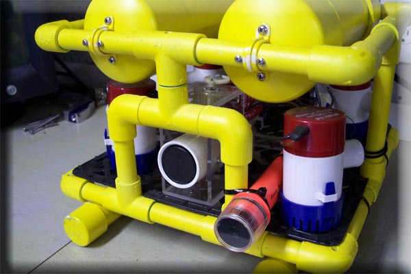
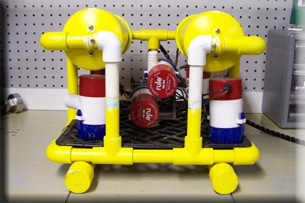
These are a few pictures of the Seafox before I started the Retrofit.
|
 |
|
I first had to modify the Frame to accept the new Manipulator and Camera Mount.
|
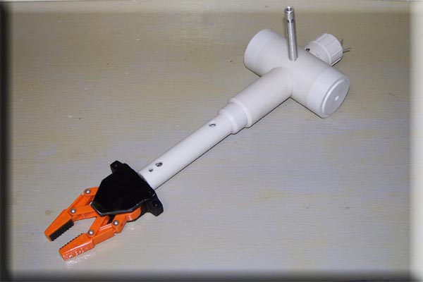 |
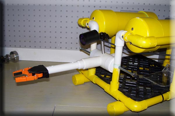
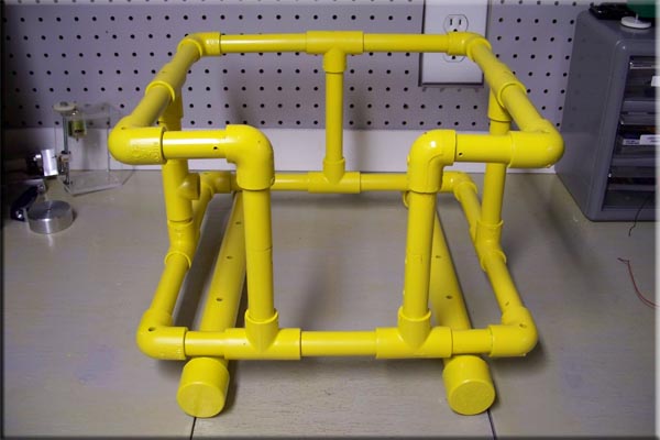
| This is the new Manipulator and Camera Mount. It was machined from common PVC Pipe and Fittings. |
 |
 |
|
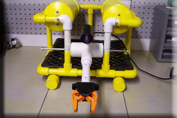
A quick test fit and everything looks good so far.
|
 |
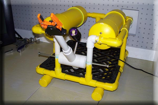 |
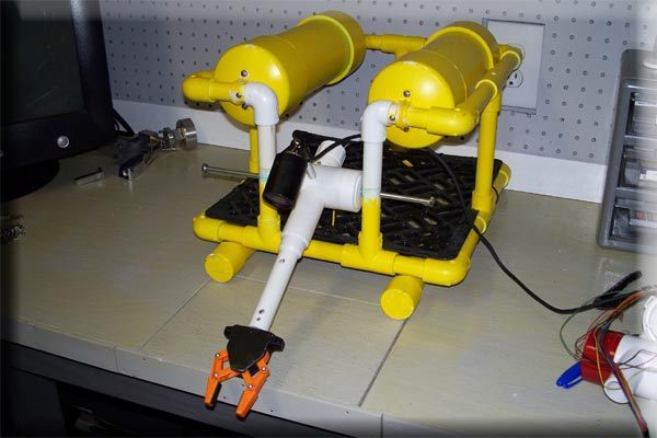
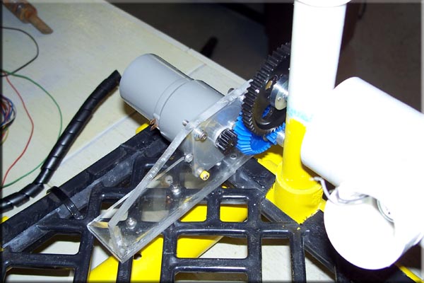
| I hoping to have the entire setup rotate almost 180 degrees up an down, but it all depends on the mechanics I come up with to rotate it. |
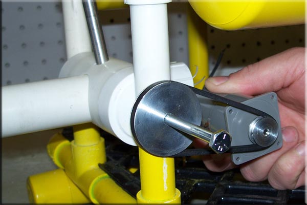 |
| I'm testing out a few methods on how to get the arm to tilt, I have this 30 RPM Airpax Motor that I tried to mounted directly to the shaft and while it worked it didn't have precise enough control. I had this belt laying around so I machined up a few pulleys to try, I pretty much knew it wasn't going to work but I figured I'd try it anyway. Well I was right and the belt slipped to much so I had to order some gears to try next. |
 |
|
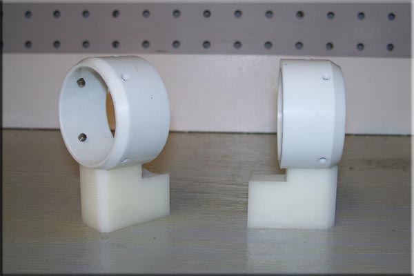
These are the Thruster Mounts I made for the rear Thrusters.
|
 |
|
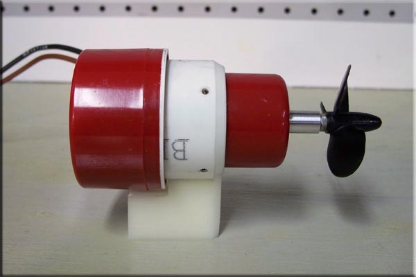
The Bilge Pump Thrusters are held in by 4 set screws.
|
 |
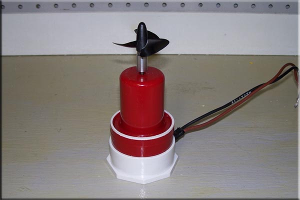
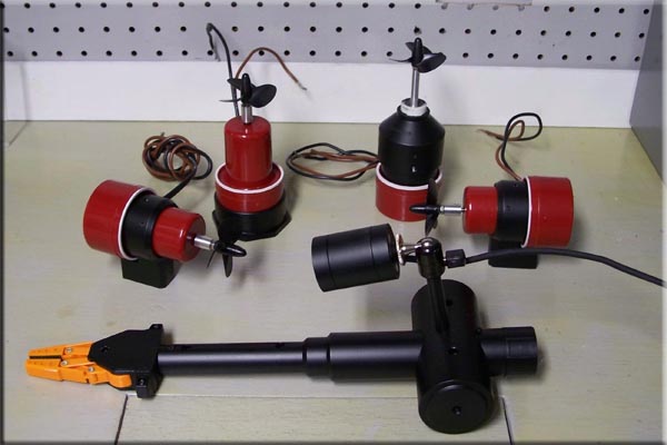
| Here are the 2 rear Thrusters, I used counter rotating props to cancel out the torque of the motors and to keep the Rov tracking straight. It might be a little over kill but it can't hurt. |
 |
|
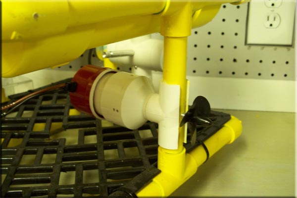
I haven't figured out final placement of the Thrusters yet, this is just another quick mock up.
|
 |
|
This is the Mount I came up with for the Lateral Thruster it will clip onto one of the vertical Frame supports and be held in place with a few screws.
|
 |
 |
| Overall I'm really not happy with it because the prop sticks outside of the frame but being a retrofit I really didn't have the room to fit all 4 Thrusters inside the Frame and still keep the props in the location they need to be. This Thruster along with the vertical Thruster have to be exactly in the center of the Frame so I really didn't have too many options without changing the entire Frame. If I moved this Thruster off center either forward or backwards the Rov would have a tendency to turn rather than just move laterally. I will probably have to put a shroud over the prop for safety sake. |
 |
|
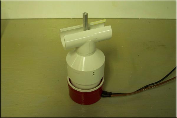
Here is the finished Vertical Thruster mount, this thruster is just press fit into the machined fitting.
|
 |
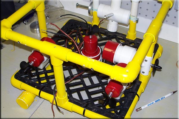 |
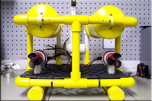
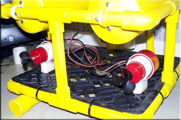
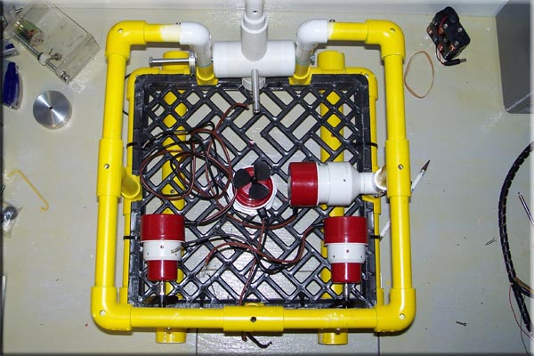
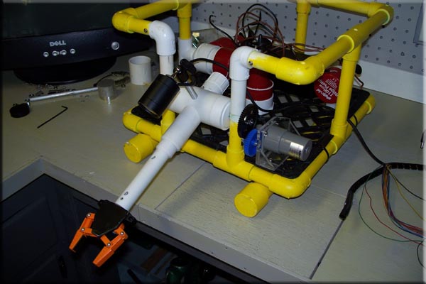
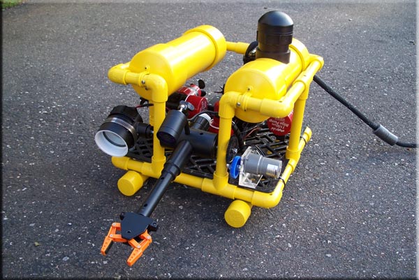
| Here is the final layout of all 4 Thrusters, this setup should still give the Rov the 4 degrees of freedom the original Seafox layout had with 6 Pumps. I drilled several mounting holes in the rear Thrusters Mounts so I can angle the rear Thrusters a bit so the Rov turns faster but I am going to wait to see how it works first, it can be changed in a few minutes in the field. |
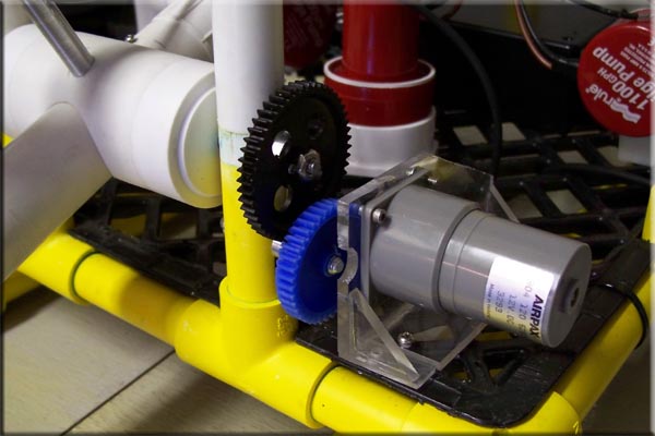 |
| My gears showed up and I came up with this simple setup which now gives me smother control over the tilt function. It may be a bit slow but I can change the ratio if I have too. |
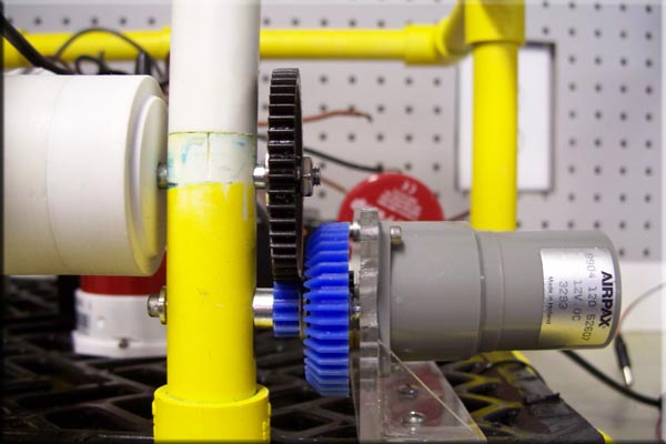 |
| I ordered several different sets of gears and lucky for me several of them had he same pitch. I used 4 gears to get the right tilt speed I wanted. |
 |
| I tried to reuse as much of the old Seafox setup as possible and this new tilt motor mount was hacked from the old vertical pump mount. |
 |
| Just like on the first setup I didn't bother to waterproof the motor this time either, it will be run right out in the water if it fails I'm out $8.00 and I'll redo it later. Over all I achieved close to the 180 degrees of tilt I was looking for. |
|
|
|
Quick Video of the first test including what the view from the camera looks like.
|
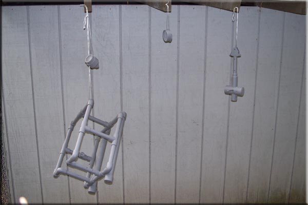 |
| I need to paint all the new parts so I decided to repaint the Frame also, getting paint to stick (or stay stuck so to speak) to PVC isn't the easiest thing so I start with a coat of primer. |
 |
|
All the new parts have now been sprayed a flat black. The Frame is still getting a few more coats at this point but will still be yellow.
|
 |
| Fresh coat of yellow on the Frame, it's not as bright of a yellow as before I wanted to tame it down a bit. |
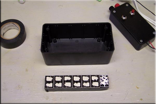 |
| This is the start of my rewiring job for the Seafox. (This is probably far from being the right way to do it but I really can't lay out a circuit board for the life of me.) I start by gluing and taping together all the relays I need. I use 6 (EP2R-B3G1) relays (4 for the thrusters and 2 for the manipulator/tilt) and 1 standard SPDT 5A Relay which will be for auxiliary lighting. |
 |
|
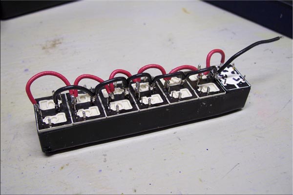
This is the main power feed wiring for the Thrusters and Lights.
|
 |
|
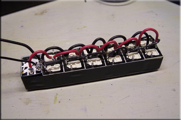
Then I wired the common positive wire for the Relays Coils.
|
 |
|
Wired in the Main 16 Gauge Power Wire and all the 24 Gauge control wires for the Relays.
|
 |
|
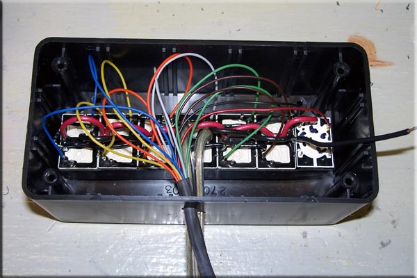
Finished wiring in the Thrusters, Aux. Lighting, and other misc. Add ons.
|
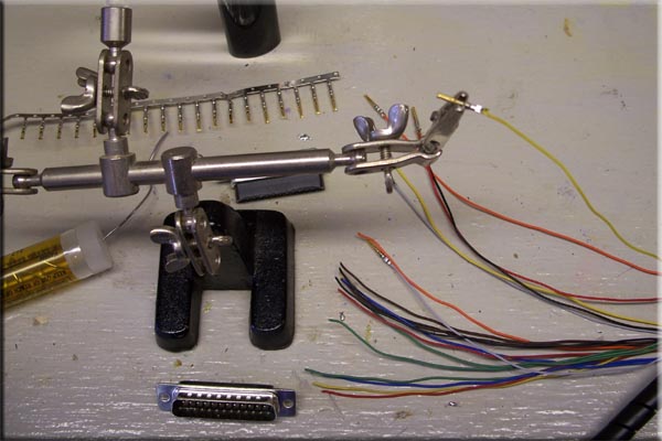 |
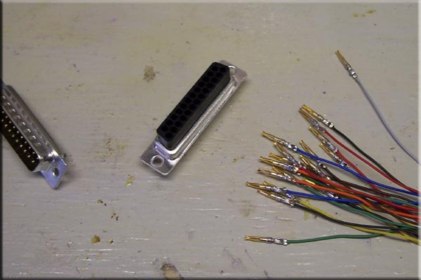
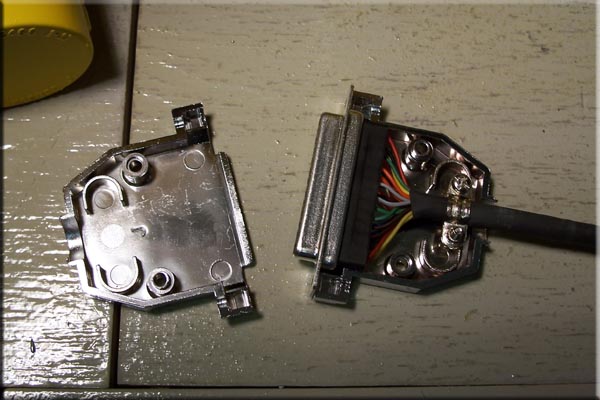
| Next came the other end of the Tether, I had to solder and crimp all the pins onto the 25 pin computer connector I used for easy disconnect. |
 |
 |
|
Next I had to figure out the pin placement.
|
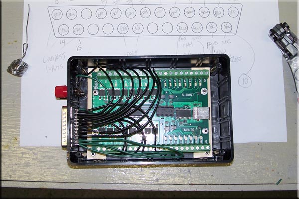 |
| I'm still using the Phidgets Board for control, it will just be used topside to interface into the laptop for now. I tested this out before on the Seafox but it had to be rewired for the new relay setup. I also have to rewrite my control program because with the converted pumps all the functions have changed. The programing my take me a few more days to figure out. |
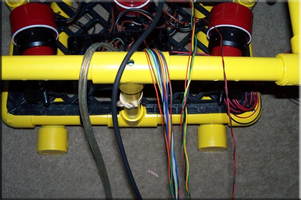 |
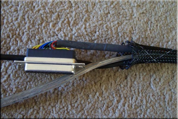
| I kept all of the old wires from the original Seafox Tether and just added one new 16 gauge pair for main power. This is the new Make Up of the Tether, it consists of (from the left) one pair of 16 Gauge speaker wire for Main Power, the Camera Cable, Twenty 24 Gauge wires (phone wire) - (14) are Relay Control wires, (4) are Compass Signal wires, (2) are Spares for some future add on. |
 |
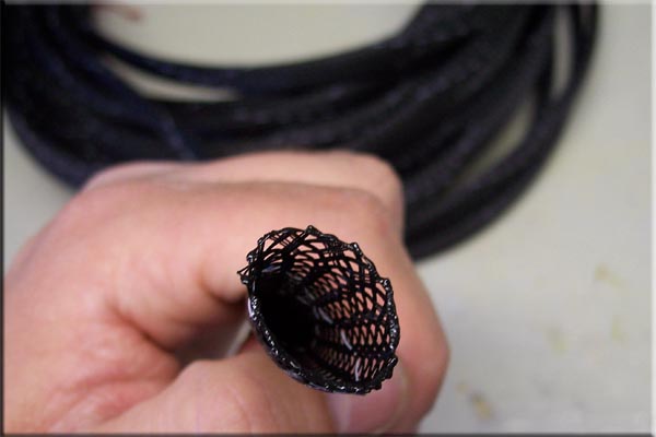 |
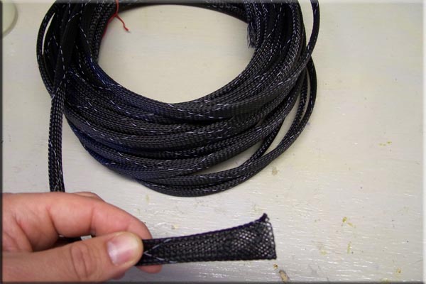
| The old 3/8" Spiral Wrap was too tight with the additional pair of 16 gauge wires and the tether would not have been flexible enough any more so I had to find something else to bundle everything together. I found this stuff at my local electronics store, which they called Expando Sleeving, I call it Snake skin because it feels like it and the way you feed it over the bundle of wires it looks like a snake eating something, you get this big bulge you have to work the entire length of the tether as you go. |
 |
| I thought it was going to be a nightmare to feed this stuff over 50' of cable but it was easy. It took me about an hour and a half to remove the old spiral wrap and only a half hour to feed this new stuff on, and that was with the above plug all ready attached. I'm not sure which I like better this stuff or the spiral wrap. The Spiral wrap was round and flexible but the wires were exposed and might be easily cut. This stuff completely covers the wires but it doesn't hold the bundle as round, the tether is still flexible but with the new power wire it doesn't twist as much as it use to and makes it hard to wrap up neatly, I probably should have split the pair of wires into two single ones. |
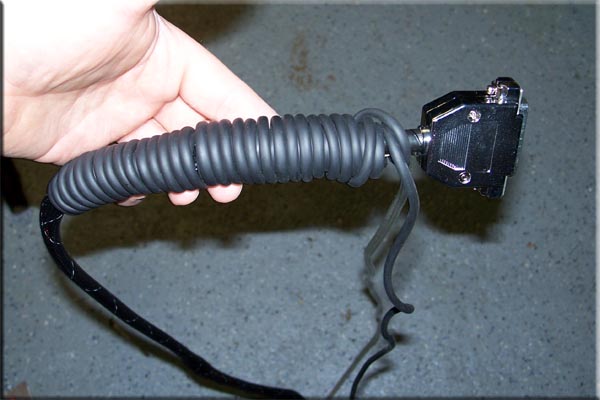 |
| My Cameras cable is 60 feet long so for now I just wrap the extra cable around the end of the Tether. |
 |
|
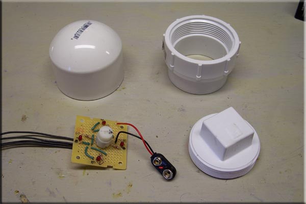
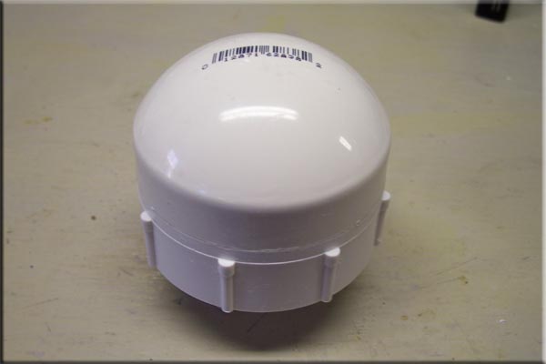
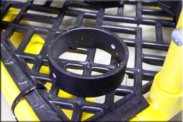
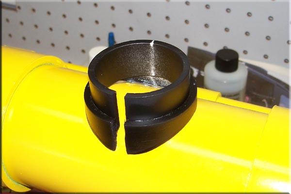
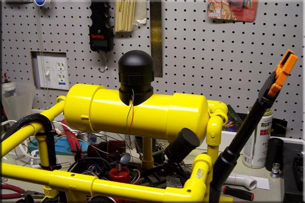
This is my Compass (I tested out before) and a few PVC pieces I will use for it's housing.
|
 |
|
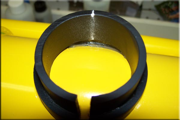
I turned the pieces down a bit on the lathe just so the housing was a bit smaller.
|
 |
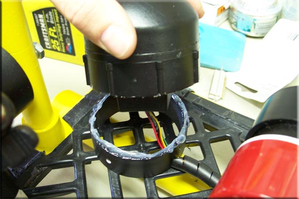
| The Compass will be attached to the plug and the Housing will be screwed onto the top of it. Here the wires have been feed threw the plug and I filled the bottom of the plug with JB Weld to it seal up. |
 |
|
Next using a little CA I glued the Compass board right to the plug.
|
 |
| After wrapping the threads with Teflon Tape and screwing on the Housing and thinking I wouldn't have to open it up again I decided to put a little silicone around the plug just for added protection. |
 |
| This is the Mount for the Compass Housing it is screwed into the grid from the bottom with two 2/56" screws. |
 |
| I was going to use two screws from the side to hold the Housing on and so it could be adjusted but decided just to use a little silicone to hold it on. |
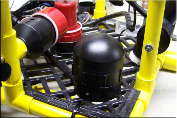 |
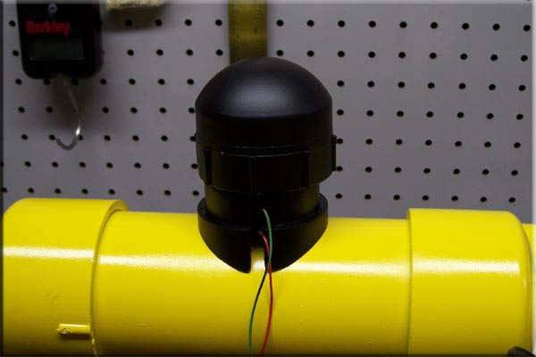
| This was suppose to be the finished Housing, I tested everything out along the way and everything seemed to work fine. Before sealing the Housing to the Mount I kept rotating it and made sure it was set to the right direction. I spun the Housing 360 degrees by hand and everything worked great (or so I thought) each of the eight points seemed to read fine. After everything was said and done I picked the whole Rov up to see it work and ....... Well it didn't. I unsealed it and spun the Housing again by hand and every thing seemed to work fine still, after pulling everything apart and opening the Housing to check the connections and hook ups I finally figured out the housing is too close to the Thrusters. The pumps must have a hell of a magnet in them because they are throwing off the Compass, After a few tests I figured out the Compass has to be around 8+" away from the nearest Thruster to work right |
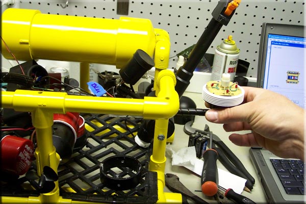 |
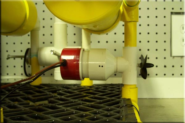
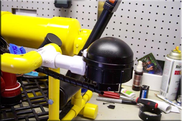
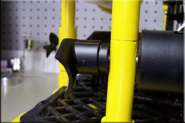
| This is how far away from the Thruster the Compass has to be to work, I'm not sure what I'm going to do yet. I might just have to mount the Housing off of the top frame where it is shown above with a short extension |
 |
| I made this Extension Mount to hold the Compass Housing off the front of the Frame and while it seemed to work ok I just didn't like how far it stuck out and it is right where one of the Flotation Pods mount, so I'm going to try a different location. |
 |
 |
 |
 |
| After a little more trial and error I found this location might work. It's strange because it's closer to two of the Thrusters than before (that's magnetic fields for you) but so far it seems to work.
The first two pictures show how I had to modify the first Mount to fit on the Flotation Pod. Once again I used silicone to stick the Housing to the Mount as well as the Mount to the Flotation Pod. The way this thing has been breaking my balls I'm sure once I get it into the water it will stop working :) so it might have to come off again. |
 |
| This was the mount I made for the Compass for off the front of the Frame but I didn't like it there so I decided to use it as a light mount. I screwed it on the other side of the Manipulator Mount so the light would also rotate with the Camera view. I was going to attach the Light Housing I did for one of the How To's just to test out some Auxiliary Lighting but I dropped the light housing today and it broke on me. |
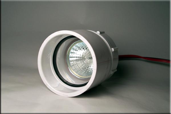 |
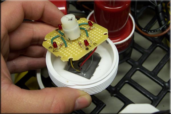
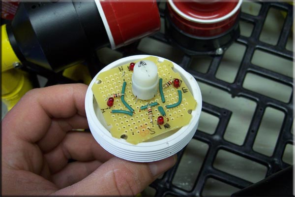
| This was the light I was going to try, I may make another housing or just make a new one with more IR Leds. |
 |
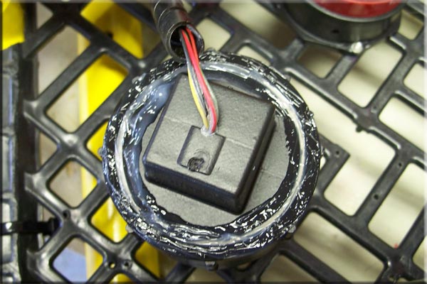
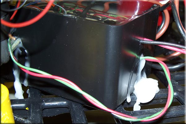
| I put a little silicone around the wire exit holes to keep the wax from leaking out while its poured in. |
 |
|
I didn't do a very good job as you can see.
|
 |
 |
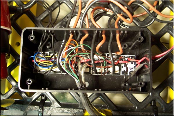
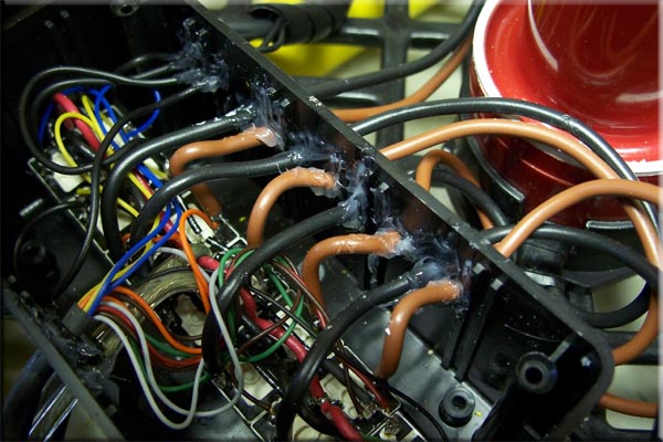
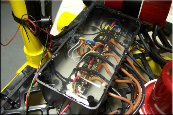
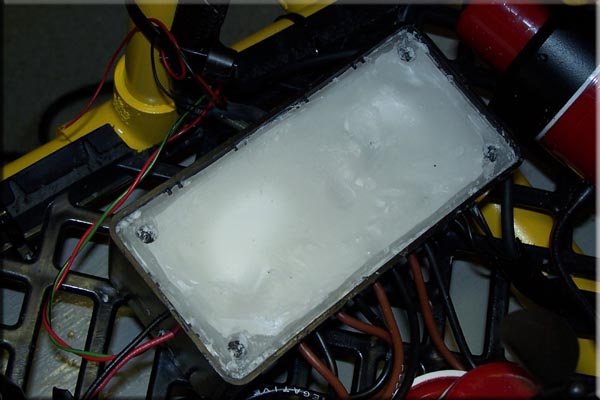
| The wax has been poured in at this point and I'm just waiting for it to harden. I won't be able to tell if everything still works until tomorrow I'm hoping for the best because if something goes wrong its a PITA to get the wax back out :) |
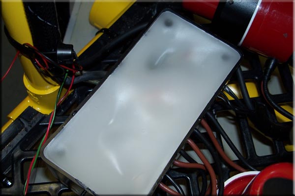 |
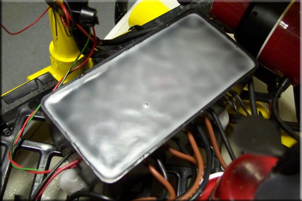
| I was a little worried the next day because there were a few spots that sunk in pretty good. I thought maybe some of the wax leaked into one of the relays but after hooking everything up and testing it out everything still worked fine so I just added a little more wax to the top. |
 |
|
After it was hardened I dug out the screw holes and around the edge and for the cover.
|
 |
|
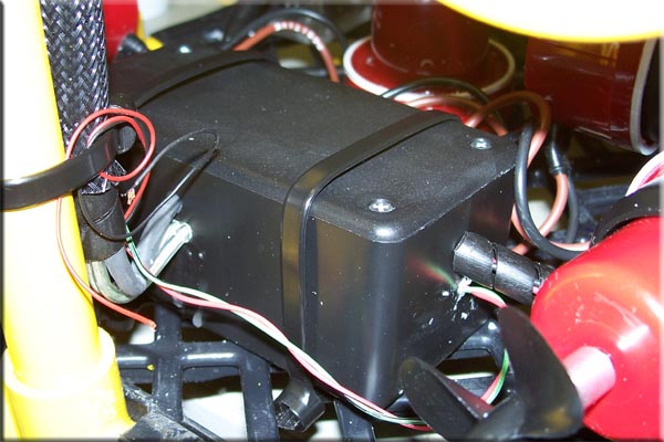
The cover was then screwed on and the Relay Box was secured in place with zip ties.
|
 |
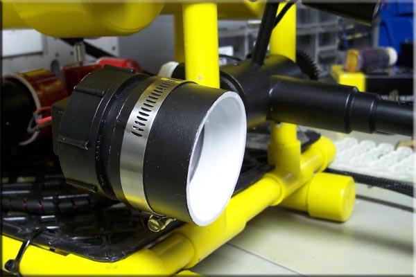 |
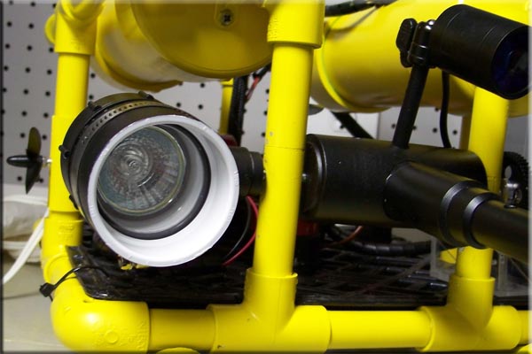
| I decided to rebuild my light housing and give it a try. It's just held on with a hose clamp so changing it will be easy if I don't like it. The light draws about 1 amp so when its on it will slow the thrusters down a bit too, which might be a good thing. |
 |
|
I did some tests in the tub tonight and everything looks good. I had the rear thrusters on an angle and the Rov turns pretty quick, it might be a little to quick, I am going to straighten out the thrusters to see if it slows the turns a bit. Using a fishing scale the Rov pulls about an average of about 2 to 2.5 lbs. in the water.
I also tested the draw, using a mower tractor battery for power (12 volts) with one Thruster on its about 4.5 amps, Both Rear Thrusters draw about 7 amps, Three a once is about 8.75, and all 4 was 9.80 the relays are powered from the same source and draw .05 to .10 amps. |
 |
| All Information, Pictures, and Material is copyright © 1998-2009 by Stephen Thone and may not be used for any personal or commercial purposes without the consent of the author. All rights reserved. The Author makes no guarantees or warranties as to the accuracy or completeness of, or results to be obtained from accessing and using the Information herein. | |||